3D Animation Workshop: Lesson 72: A Challenging Model
|
|
Lesson 72 - A Challenging Model - Part 2
Next, I was on to the neck. From the very start, I identified the scroll as the most difficult part of the entire project. This was not only because I had to produce the characteristic spiral, but also because the same unit is used for the peg box.
The best approach to the scroll turned out to be path deformation. I drew a NURBS spline in the shape of the desired spiral. Then I created straight NURBS surface with the characteristic edges and an exaggerated central ridge. I was then able to use path deformation to "roll" the surface up along the defined path. This turned out to be a very workable approach, because I was able to tweak the shape of the surface by editing the path curve.
The downside of the method, however, was that I could not effectively produce the terminating center of the spiral without a lot of distortion. So I compromised by creating a separate surface as a "plug." As a separate object, it could not blend seamlessly into the rest of the scroll, but the seam was tiny and could be positioned where it would not be readily visible, so I accepted this compromise.
It was relatively straightforward to trim out a hole in the top for the pug box and extrude down the sides (and create a separate surface for the bottom). The pegs were lathed (revolved) curves, and trimmed on both sides. The trimmed holes we filled with matching curved surfaces. In the screen shot below, you can see small white cracks where the two trimmed surfaces meet on the pegs, but these cracks were eliminated by edge merging in the final render.

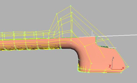
The curvature in the neck took some serious thought. I needed a nice smooth bend, but also needed sharp edges. There were many possible approaches, but I decided to create single loft surface with a bend because it was easy to draw the component curves. Then I started trimming to get the sharp edges. I could get by with "only" four trims because some of the bulging curvature would end up being hidden inside the body of the violin. The following picture shows the surface (with all its CVs) and the trims.
To build the fingerboard, I used the trim curves that defined the top of the neck as guides along which to extrude a curve. Of course, the fingerboard needed to be much longer than the neck, but once I had the basic surface, I could extract curves from it, elongate them, and then rebuild the surface from the longer version. To close up the top of the fingerboard, I extracted a curve off the end of the surface, and used it to loft a little separate capping surface. Since the cap was built from a curve right off the fingerboard, it was easy to join both surfaces into a single seamless unit.

| To Continue to Part 3, or Return to Part 1, Use Arrow Buttons |
|
Created: August 2, 1999
Revised: August 2, 1999
URL: https://webreference.com/3d/lesson72/part2.html
 Find a programming school near you