3D Animation Workshop: Lesson 70: MAX NURBS--Finishing the Piston
|
|
Lesson 70 - MAX NURBS--Finishing the Piston - Part 2
MAX 3 (slated for release shortly) has added surface tangency control to its loft surfaces. In other words, we should have been able to simply skin (loft) between the trim curve and the other curve, and instruct MAX to create a smooth blend into the flat dark-green surface. If this technique can work, it's a great convenience. But our results with this technique were flawed, and Dino and I were forced to stick with the established blend surface approach. We were still using a Beta version of the program, so the lofting approach may well work out when the final release of MAX 3 arrives.
The next step was to join the two surfaces (red and orange) into a single one with a rounded edge. You may be asking why we didn't create a single surface to begin with. The main reason was that we needed to create a blend surface to get the desired tangency, and a blend surface can only connect two curves. But even if we had been able to use the loft approach, the result would have required too much tweaking. One of the most important things I've discovered when using MAX NURBS is that you can often get better results by creating multiple surfaces and joining them than by creating a single surface in the first place.
Before joining the two surfaces, we rebuilt the three curves from which they were composed so that they had precisely the same number of control vertices (CVs). This isn't always necessary, but it's generally a good idea. Then we joined the two surfaces to create a single one. You can choose to "join" or "zip" the two surfaces under the Join command. In this case, both choices were very similar, but in other cases I've noted that one of the two produces a markedly cleaner result.

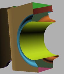
After joining, the two surfaces became a single independent surface, controllable with surface CVs, as shown in the image above. To get a rounded lip, we eliminated a couple of circular "rows" of CVs where the two original surfaces met. This softened the hard edge, as you can see in the image above.
The next job was creating an identical surface for the inside of the piston. The following image shows the inside with the new surface in blue. As with the outside one, it was created in two pieces and joined. Finally, the yellow surface was lofted between the inner curves on the outside and inside. The hole and its rounded hubs were complete.
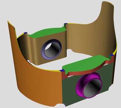
It was time to mirror the new one-quarter piston around to build the complete version. Dino and I were pleased with the result. There were 14 separate surfaces for each quarter, and therefore 56 surfaces in the whole thing. Pretty complicated, really.
| To Continue to Part 3, or Return to Part 1, Use Arrow Buttons |
|
Created: July 3, 1999
Revised: July 3, 1999
URL: https://webreference.com/3d/lesson70/part2.html
 Find a programming school near you