3D Animation Workshop: Lesson 67: Basic MAX NURBS Patches | 2
|
|
Lesson 67 - Basic MAX NURBS Patches - Part 3
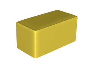
Let's say we want to model a car body. A basic unit of thought for such a model is a quarter of the entire body, composed of three perpendicular surfaces meeting at curved edges. If we can get a good general conception of how to structure such a unit, we can shape it in a wide variety of ways.
Let's start with a radial approach. We draw a curve in a top view. Then we copy it and scale it to zero length and position it in the same plane as the first curve. Then we copy the first curve and translate it down. The perspective view below may be a little confusing, but it highlights the difficulty of working with NURBS curves floating in empty space. They can be very tough to visualize.

But with NURBS you always have to render to see the naked truth. The edges look terrible!
Everything about NURBS requires tedious tweaking. I reduced the Tension on the middle curve, translated the zero-length curve upward, and scaled out the bottom curve. This rounded things out, and it looked perfect in a wireframe view. But, now there's a new horror in the render.
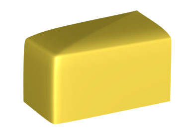
The top of the surface looked likes it's creased, but it's not. Here's where all that technical stuff from the previous lesson is going to seem real important all of a sudden. If we render in wireframe to see how the NURBS surface was tessellated into polygons, things become clear.
The radial structure created a dense region of knots. This was necessary to hold the vertical edge, but as it continued across the top, the resulting polygonal density confused the renderer into illumination errors on a perfectly smooth surface. The limitations of the current MAX renderer with NURBS (even in MAX 3, in which these renders were made) are a serious frustration. If the Mental Ray renderer arrives for MAX as promised, these issue will hopefully evaporate.
To tweak the basic structure, I replaced the zero-length curve with a straight curve and re-lofted (adjusting Tension as well). The result has the same basic structure, but is not as compressed. In the following image, the three curves are in red.
This produced a much better tessellation in polygons, which eliminated the illumination flaws.
| To Return to Parts 1 and 2, Use Arrow Buttons |
|
Created: May 12, 1999
Revised: May 12, 1999
URL: https://webreference.com/3d/lesson67/part3.html
 Find a programming school near you