3D Animation Workshop: Lesson 39: Softimage--NURBS Blending
|
|
Lesson 39 - Softimage--NURBS Blending - Part 2
In NURBS modeling, we can't effectively pull small units of the subsurface out of the main surface. Thus branching architecture is achieved by creating separate objects and aligning them to the main object is a manner that, hopefully, appears seamless. I stress the word "hopefully" because the process of blending NURBS is difficult, frustrating and often unreliable. It is the hardest thing to learn in NURBS modeling, and is particularly difficult in Softimage. To achieve even the simple examples we will examine here requires considerable practice. The difficulties of NURBS blending (as the process of merging NURBS surfaces is most generally called) have discouraged countless crusaders into the realms of Softimage.
Let's look at a couple of traditional Softimage methods for blending. Softimage has implemented a new NURBS blending tool that we will not examine, but which promises (as the kinks are worked out) to improve the situation. The two traditional methods will help us to understand a great deal about Softimage modeling generally.
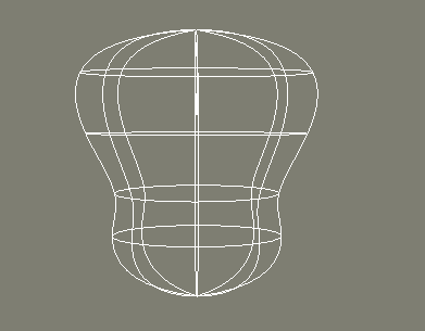
Here's a wireframe of a stylized torso, to which we want to attach an arm. The torso is a closed NURBS surface. The u direction curves (the horizontal ones) are closed, and the v direction ones are open, but their endpoints are capped together at the top and bottom. This torso was created by revolving a NURBS curve in a circle, and then scaling the resulting object to flatten it from front to back.
The next step is to create two concentric circles that are projected onto the shoulder area of the torso. The inner projected one is used as a "trim" curve. It cuts out the region inside it. The outer projected curve simply lies on the torso surface. Another circle is the created outside the torso to create an arm unit. The following two wireframes, one in perspective and the other a front orthogonal view, are worth careful examination.
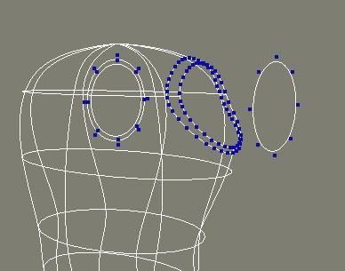
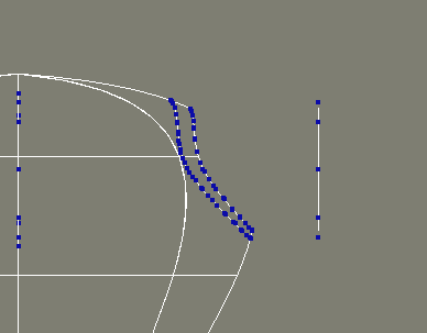
Note how many points are generated in the projected curves in order to get them to follow the contour of the torso precisely. To create the arm unit, the two projected curves are extracted. In other words, copies of these curves are made that are no longer attached to the torso. These are then skinned together with the arm circle to create a new NURBS surface for the arm. Like so.
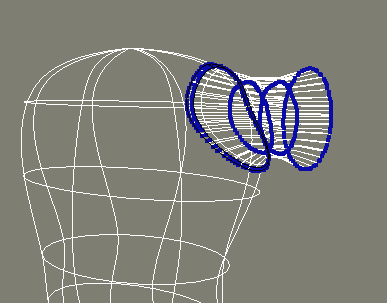
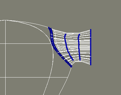
Notice how, when using NURBS, the skinned curves need not all have the same number of points. The skinning procedure will add any necessary points to curves that lack them.
The reason we used two concentric curves on the torso was to create a blend. We are seeking to create a small sleeve-like region where the arm surface overlaps the torso just a little bit. How did it turn out? Let's look at a render.
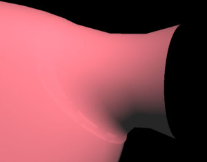
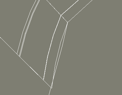
Now that's ugly! The blend region of the arm surface at the bottom is passing underneath, rather than covering, the torso surface. A wireframe close-up of this region reveals the problem. Can you see it?
There's nothing automatic about blending techniques. It takes some hand tweaking of the points around the blend region to get an acceptable result. Here's a wireframe and a render.
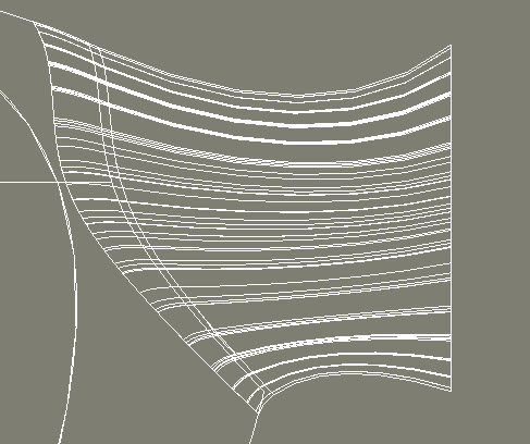
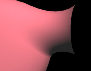
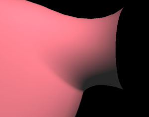
This looks pretty good, but it can be improved with a transparency mapping technique that fades out the edge of the arm portion of the blend. This makes for a more seamless look. The difference is subtle, but noticeable.
Let's try another approach to blending.
| To Continue to Part 3, or Return to Part 1, Use Arrow Buttons |
|
Created: April 28, 1998
Revised: April 28, 1998
URL: https://webreference.com/3d/lesson39/part2.html


 Find a programming school near you