3D Animation Workshop: Lesson 15: XX | 2
|
|
Lesson 15 - Onward and Upward - Part 2
The alternative to a perspective view is an ORTHOGONAL view, also called an orthogonal projection. The word orthogonal means, essentially, "straight." Unlike a perspective view, which can be from any point in the scene, an orthogonal view is inherently along one of the three coordinate axes. Thus there are front views (along the z axis), side views (along the x axis), and top views (along the y axis). There is no viewpoint in space, and therefore no perspective distortion. If we are viewing orthogonally in the front view, facing the xy plane, all points at a given location in x and y are plotted to the same location in the view, regardless of their location in z. The orthogonal view eliminates the concept of distance from the viewer. In an orthogonal view, the railroad tracks never converge.
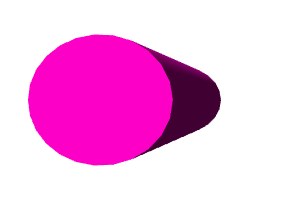
Here is a front orthogonal view of the cylinder, taken from a screen shot of the application. This is necessary because 3-D applications render from a camera viewpoint, which is always a perspective projection. The screen shot is useful in showing the grid that is used in modeling. Without a grid, it can be very hard to make sense of an orthogonal view.

In this view, there is no distortion. The back side of the cylinder is the same size as the front. But a consequence of this is that we can no longer tell that there is a back side at all. All the points and lines on the front exactly cover the corresponding lines and points on the far side of the cylinder, and there is no suggestion that this is a 3-D object. On the other hand, the sides are straight. To understand this object in three dimensions, we must be able to look at the three different orthogonal views at the same time, preferably on one screen. The experienced 3-D artist assimilates the three views at a glance to synthesize the sense of a single object in coordinate space. But this skill does not come easily or quickly, and the student should not expect it to.
Now that we have some sensitivity to the difficulties of perspective viewing, and of the nature of the orthogonal alternative, let's get back to modeling the lid of the chest.
The cylinder we used was symmetrical. In other words, the cross-section was a perfect circle. But this is not quite right for our chest.
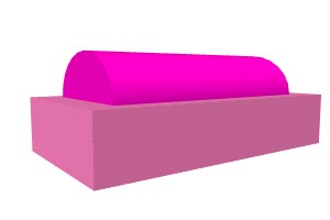
Here is a render of the lid alone.
Notice that the side face is squashed. It is not as tall as it is wide. To get these proportions, we must change the dimensions of our primitive. The cylinder remains 1 meter long on its extrusion path (the x axis). But the cross-section radius is now made smaller in the y dimension (200 mm) than it is in the z dimension (250 mm). This idea that one can adjust the radii of a circle differently for the two dimensions should be intuitively familiar to those who use 2-D vector graphics (drawing) programs such as Corel Draw or Adobe Illustrator. In this way, all possible oval shapes can be made in two dimensions, and effectively extruded into the third dimension.
Here is the squashed cylinder in wireframe and shaded renders. Both are perspective views from an angle that helps us to grasp both the oval shape and the sense of depth.

Notice that even with smooth shading, the rounded face still reveals sharp edges. It is, of course, not a true circle, but an approximation made up of short line segments, as can be seen clearly in the wireframe. At this rendered size, the defect is not all that evident to those who are not accustomed to looking for it. But at a larger size, it might become obvious, and thus we might be forced to make our cylinder with twice as many sides to disguise the problem. This concept of "aliasing" is common to all digital graphics (and all digital media). In the final analysis, a computer screen or other digital medium is composed of discrete units. Smooth transitions of color or shape are possible only because the unit size is so small that the human eye can no longer discern it. If the individual unit is discernible, it must be made smaller by an increase in resolution. Creating more sides to a polygon is a method of increasing the resolution of the geometric surface.
We need only the top half of the cylinder. How do we get it? You guessed it! Boolean subtract.
We create a primitive box with dimensions big enough to enclose the volume of the cylinder that we wish to subtract. The top of the box is positioned flush with the xz plane (the horizontal plane).

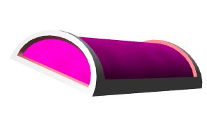
After subtracting, the bottom of the object is bounded by a flat, rectangular, polygon. Even though we subtracted a volume, the object remains completely closed. This is an important advantage of using Boolean subtraction where possible. The light pink surface was taken from the subtracting box. Having a different surface properties already assigned to this portion of the lid is going to help us out in the long run.

Now we have to carve out the inside of the lid.
| To Continue to Part 3, or Return to Part 1, Use Arrow Buttons |
|
Created: July 28, 1997
Revised: July 28, 1997
URL: https://webreference.com/3d/lesson15/part2.html
 Find a programming school near you