3D Animation Workshop: Lesson 15: XX
|
|
Lesson 15 - Onward and Upward - Part 1
In this lesson, we'll continue working on the model of the chest we began in the previous lesson. If you haven't read the previous lesson, or even if you have, you'll want to review Lesson 14 before getting started here.
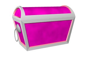
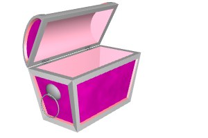
Here, once again are two rendered views of the finished chest.
In the last lesson, we reviewed BOOLEAN OPERATIONS generally and used a basic Boolean Subtraction to carve out the interior space of the box portion of the chest. I suggested at the end that the same approach might be used to create the lid.
As always, we start by thinking about what kind of PRIMITIVE offered by the application is available to get us started. For the box we used a box or cube primitive. The lid is basically a cylindrical tube sliced in half along its length.
So we start with a cylinder primitive. To make things easier down the road, we'll start with the same basic dimensions as the box on which the lid is to fit. Let's make the cylinder 1 meter long on the x axis. Because this is a cylinder, we must define the length of the cylinder along an axis, and then define the radius of the circle that represents the cross-section. Imagine a flat circle of a given radius being EXTRUDED along a straight path of 1 meter. We could actually perform such an extrusion of a 2-D circle polygon to create the very same cylinder, but using the primitive is easier. Let's make the radius of the cross-section .25 meters (250 mm). The diameter of the cross-section circle is therefore .5 meters (500 mm). Make sure you've thought this through before you go on.
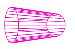
We'll be working in wireframe views here because learning to visualize in wireframe is a critical skill, and one not easily mastered. Here is a wireframe view rendered from a camera placed directly in front of the cylinder
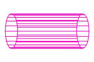
Huh?!
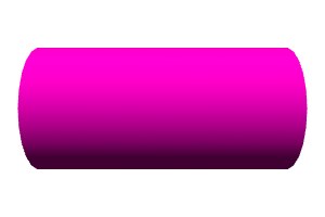
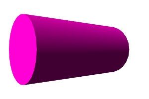
We'd better look at a shaded render of the very same scene to get oriented.
Stop and take a moment to understand these two images and how they correspond. The wireframe view is terribly confusing. The main problem is that the image is in true perspective. In perspective view, as our eyes or a camera sees in the real world, objects contract with distance. This is precisely how we judge the distance of an object, comparing its apparent size with our own judgment of its true size. Looking down railroad tracks, we see them appear to converge at a single point in the infinite distance. We know this is an illusion. This is the nature of perspective. Thus in our wireframe view of the cylinder, the back side of the cylinder appears smaller than the front side, and the faces on the side appear to converge toward the center. Even this interpretation can been very difficult to see, but try to recognize it in the image. The problem is (as with many visual tricks associated with the work of M.C. Escher) the mind's effort to make sense of conflicting interpretations, and its bouncing back and forth between them.
Notice, however, how perspective distortion helps us to understand the shape in the shaded view. The vertical ends appear to bulge out in the middle. Our mind interprets this to mean that the middle horizontal of the object is closer to us than the top or bottom horizontal edges. Without the bulge (and particularly without the shadowing), we would interpret the image as a flat rectangle rather than as a rounded surface bulging out toward us. The 3-D artist must become sensitive to all the clues that reinforce the illusion of objects occupying 3-D space.
If we rotate the cylinder around the vertical (y) axis, the true nature of the shape is more comprehensible, though the perspective wireframe is still confusing.
But, fortunately, there is another way of viewing wireframes.
| To Continue to Parts 2 and 3, Use Arrow Buttons |
|
Created: July 28, 1997
Revised: July 28, 1997
URL: https://webreference.com/3d/lesson15/
 Find a programming school near you