3D Animation Workshop: Lesson 117: Welding Vertices in MAX 4
|
|
Lesson 117 - Welding Vertices in MAX 4 - Part 1
Let's finish our brief tour of the new Editable Poly object in MAX 4, begun a a few lessons back.
Polygonal modeling is basic, and the serious modeler understands his or her polygonal modeling toolset completely. This current series of lessons represents nothing other than my own very careful attempt to clarify for myself the ways in which the new generation Editable Poly object differs from the traditional Editable Mesh. It's smarter to obtain this understanding with simple tests, than by winging it in a real modeling project with all of its practical complications. I like to understand my tools, at least in a fundamental way, before I being a serious task.
Thus far, the Editable Poly has proven more flexible and easier to use than Editable Mesh in every respect. Let's focus on a contrast between the two that is a bit more confusing.
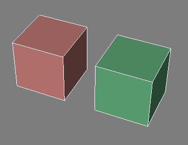
Once again, we see an Editable Mesh cube (in pink) on the left and an Editable Poly version (in green) on the right.

Welding vertices is a basic operation in all polygonal modeling applications. The traditional approach in Editable Mesh is easy to use and commonly practiced. In the Vertex sub-object mode, you have two welding choices - Selected and Target.
To use the Selected approach, you first select all the vertices you want to weld into a single vertex. Then you press the Selected button to weld them. All vertices that are within a threshold distance of each other are welded. You often have to adjust the distance spinner next to the button to make sure that you've set an adequate distance.
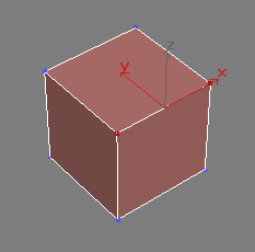
Here's the Editable Mesh with two vertices selected.

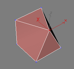
After setting a distance spinner to a value large enough to include the distance between these vertices, I press the Selected button. The edge between the two vertices disappears, and the two vertices merge into one at the midpoint between their original distances.

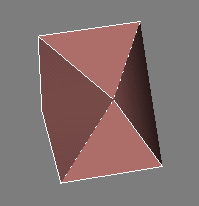
This looks simple enough, but let's examine things a bit more carefully because, after all, this is MAX. If we switch to Edge sub-object mode, we see peculiar dotted edges. What's that all about?

| To Continue to Parts 2 and 3, Use Arrow Buttons |
|
Comments are
welcome
and brought to you by webreference.com
Created: April 24, 2001
Revised: April 24, 2001
URL: https://webreference.com/3d/lesson117/


 Find a programming school near you