3D Animation Workshop: Lesson 111: From Geometry to Pictures
|
|
Lesson 111 - From Geometry to Pictures - Part 1
Let's finish up the overview of the rendering process that we began a couple of lessons ago. Thus far, we've considered only the geometry end of the process, in which all of the vertices of all of the objects in the scene are transformed into a coordinate system common to the entire scene  the world coordinate system. Then, all of these vertices are further transformed into a camera coordinate system, based on the location and direction of the camera. We are all set up to "take the picture."There are a number of processes needed to produce a rendered image. For one, we need to determine what objects are in the camera's field of view so that we don't bother with objects and vertices that cannot be seen. This process involves both culling and clipping.
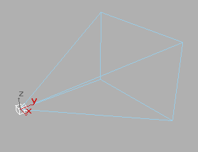
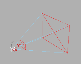
I'll use some screenshots from 3D Studio MAX to give you the idea. Objects will be rendered if they are within the view volume - a pyramid emerging from the front of the camera.

Notice the axes of the camera coordinate system. The y axis here points in the direction in which the camera is looking, and the x and z dimensions represent the render plane perpendicular to it (equivalent to the film plane of a real camera). Unfortunately, MAX violates basic conventions about coordinate axes. In every other system, and in the common language of computer graphics, the camera points in its z direction, and x and y are the horizontal and vertical dimensional of the render plane.
Note also that there is a visible base to this pyramid. This is just for display purposes here, as the view volume can extend infinitely for all practical purposes. But, if we wish, we can define front and back clipping planes to further limit the view volume.

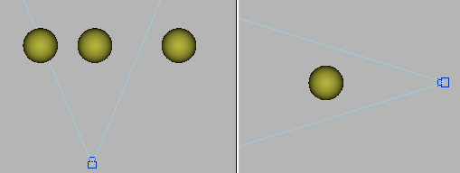
Consider three objects from two views. One is completely within the view volume. Another is partially with it, and the third is entirely outside the view volume.

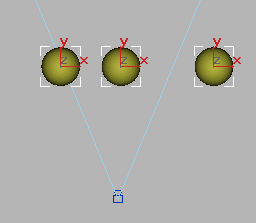
Before we project the vertices of these objects onto the rendering plane, we'd like to completely eliminate (cull) the object that is wholly outside the viewing volume. The easiest way to do this is to test whether a bounding box enclosing each object intersects the viewing volume.

This is not a foolproof method because a bounding box can intersect the viewing volume even if no part of the enclosed geometry does, but it works well enough for basic culling.
| To Continue to Parts 2 and 3, Use Arrow Buttons |
|
Created: January 30, 2001
Revised: January 30, 2001
URL: https://webreference.com/3d/lesson111/


 Find a programming school near you