3D Animation Workshop: Lesson 111: From Geometry to Pictures | 2
|
|
Lesson 111 - From Geometry to Pictures - Part 2
The harder task is to find objects that are not wholly within the view volume and clip them to eliminate the excess. It's more than a matter of eliminating vertices that fall over the edge. We also must create new vertices right on the edge of the view volume and hook them up to the remainder of the geometry. When the process is done, we should be left only with exactly the geometry (vertices, edges and resulting polygons) that fit within the view volume.
Now we are ready to take the vertices and project them onto the rendering plane. This is the step that takes us from 3D space to a 2D image of that space from a single point of view. Let's consider only perspective projection, and not parallel projections used to create orthogonal views.
The following image demonstrates the basic concept using tools from within the MAX interface.
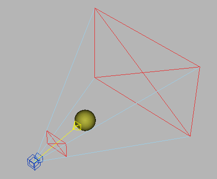
Ignore the back clipping plane, which is included only for visual clarity rather than function. Consider the front clipping plane as the rendering plane. (This is NOT what the front clipping plane actually does, but it is useful here because it shows us a slice of the view volume perpendicular to the viewing axis). In a crude but basically accurate way, imagine the front plane as a 2D screen composed of pixels. You can also imagine a plane of glass, like window, placed in front of the camera.
If we draw a straight line from any vertex in the scene to the camera, it must pass through a point on the 2D rendering plane. This is precisely how we project a vertex onto the plane, and the pixel at that point will correspond to that vertex in the 3D scene. When you have this idea  which is really very simple  you understand quite a bit.
Of course, there are likely to be pixels that project to locations on the mesh that are between vertices. We can figure out precisely where these locations are on the mesh by interpolating between the known locations of the vertices that surround it. We can do this with absolute certainty if the mesh is composed entirely of triangles, because each triangle is inherently flat (planar).

| To Continue to Part 3, or Return to Part 1, Use Arrow Buttons |
|
Created: January 30, 2001
Revised: January 30, 2001
URL: https://webreference.com/3d/lesson111/2.html
 Find a programming school near you