3D Animation Workshop: Lesson 102: My Modeling Secret
|
|
Lesson 102 - My Modeling Secret - Part 1
In our last lesson, we considered the subject of subdivision surface modeling in 3D Studio MAX in general terms. This time, I'll present an approach to subdivision surfaces in MAX of very broad significance. Once we understand it, we can give it a shot in the context of character modeling in the next lesson.
In my experience, subdivision surface modeling works best when the entire control mesh is built of quads (four-sided polygons). Mixing triangles with quads generates irregularities in the subdivided mesh. In some cases, these irregularities do not create noticeable problems in the rendered result, but I make it a personal rule (some would say, an obsession) of maintaining a fully quadrilateral mesh to the greatest extent possible.
There are three ideal elements for subdivision surface modeling. First, you must be able to extrude polygons to create branches. Second, you must be able to add new vertices by cutting through the control mesh in a way that doesn't destroy your quadrangular structure. Third, you must be able to see the smoothed version of the geometry as you edit the vertices of the control mesh.
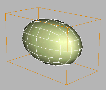
Standard subdivision surface modeling in MAX, using an Editable Mesh cage, offers the first and third of these elements. But cutting up an Editable Mesh control mesh can be very difficult and frustrating. Let's consider the simplest subdivision surface, a Editable Mesh box with MeshSmooth NURMS applied.

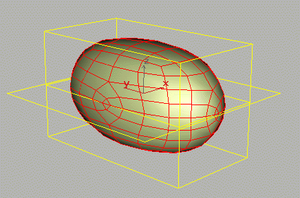
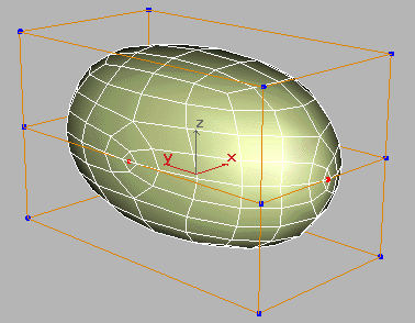
Note the regularity and quad structure of the subdivided surface. So far, so good. But we'll need more vertices to model this into anything worthwhile. To maintain a quad structure for the control mesh, we need to divide edges in a given row or column all the way through the model. Our first guess might be to apply the Slice Plane tool (in the Editable Mesh toolset). This is a clumsy tool in any case, but note how it screws up the mesh of the subdivision surface.

What happened? All MAX geometry is ultimately built of triangles, and a MAX quad is composed of two triangles. The Slice Plane tool is cutting through the invisible diagonal edges running through all the quads and creating unwanted vertices. This not only damages the regularity of the subdivision surface, but more importantly, makes the subsequent modeling process impossibly difficult. Look carefully at the following image, which shows the vertices created by the cut. All we wanted was a horizontal row of four vertices at the four corners of the box, but we got additional vertices in the center of each edge, highlighted here in red.

There must be a better way.
| To Continue to Parts 2 and 3, Use Arrow Buttons |
|
Created: September 26, 2000
Revised: September 26, 2000
URL: https://webreference.com/3d/lesson102/


 Find a programming school near you