3D Animation Workshop: Lesson 64: Introducing MAX NURBS | 2
|
|
Lesson 64 - Introducing MAX NURBS - Part 3
The next big issue to tackle is the distinction between dependent and independent sub-objects.
Every NURBS implementation has some version of what is called "relational modeling" in Softimage. In MAX, when a surface is created from curves, the surface is a dependent sub-object. This means that if you edit the curves, the surface will update. For example, the surface we just made by extruding the curve is still dependent on the curve. If we edit the curve (by moving it's CV's) a new extrusion is made, based on the new shape of the curve. Like so.
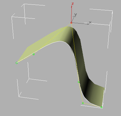
So long as the surface is a dependent object, its shape is controlled entirely by the curve from which it was extruded. If you select the surface and convert it into an independent surface (by pressing the Make Independent button), two critical things occur. First, the modeling relation between the curve and the surface is broken. Editing the curve no longer affects the surfaces.
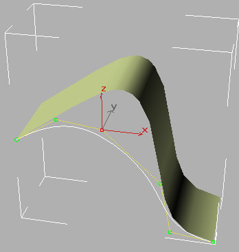
The second major result of making the extruded surface independent is that the surface is now controlled by a network of surface CV's running in the u and v directions. I've switched to a wireframe view to make the CV lattice easier to see.
Notice how the wireframe displays white isoparametric lines directly on the surface. These are simply to help you discern the shape of the surface, and have no editing powers. You can freely alter the number of these lines in the Surface Approximation rollout found at the NURBS Surface object level.
By selecting and translating the surface CV's, you can edit the shape of the surface.

Observe something important that has occurred as the result of this edit. Prior to the last edit, all of the isoparametric display lines in each dimension were identical. All of the v direction lines were the same curved shape, and all of the u direction lines were straight. This is the necessary result of extruding a single curve in a straight line, as we did to create the surface in the first place. But after the edit, the v lines change shape as they cross the surface in the direction of the extrusion. Likewise, the u isolines change shape as they cross the surface in the direction of the original curve. This is an initial glance at how a network of curves of varying shapes can define the curvature of a surface.
.Take a moment to straighten out your u's and v's. These concepts can be very difficult to get used to. Remember, the original curve used to make the extrusion defines the u direction. Thus the u isolines run perpendicular to that curve. Think of it this way: Each of the u isoparametric lines represents a constant value in the u directionÂall points on that line have the same values in theu direction, but different values v direction. Just keep at it until it starts getting familiar.
We'll pick up from here next time.
| To Return to Parts 1 and 2, Use Arrow Buttons |
|
Created: Apr. 14, 1999
Revised: Apr. 14, 1999
URL: https://webreference.com/3d/lesson64/part3.html
 Find a programming school near you