3D Animation Workshop: Lesson 64: Introducing MAX NURBS
|
|
Lesson 64 - Introducing MAX NURBS - Part 2
Getting started in NURBS modeling means running on two tracks at once. You must learn the principles of NURBS modeling that transcend, and are independent of, any specific implementation. But you must also learn the ins and outs of the implementation you are using, which can be quite a challenge in itself. NURBS is new enough to where standards have not yet firmly developed. MAX, Maya and Softimage (not to mention the outstanding Rhino modeling program) all have their own approaches to NURBS. We'll work on both fronts together, introducing NURBS modeling concepts with special reference to MAX's toolset.
NURBS are ideal curves whose shapes are governed by control vertices. The control vertices, other than those at the start and end, do not lie on the curve.
To start thinking in NURBS, consider the length of this curve as defining the u direction. The geometry of curved surfaces treats a curve as the topological equivalent of a straight line. If you were a very tiny person standing on the curve and walking along it, you could not distinguish it from a straight line. Sound funny? Well, it's just the way a person walking on the earth does not perceive that he or she is on the surface of a sphere. Our only clue is the horizon, which recedes as we approach it. In Euclidean geometry, lines are straight within our conventional and intuitive understanding. In the non-Euclidean geometry of curved surfaces, the distinction between straight and curved lines is disregarded.
Any NURBS surface has area in the directions u and v, just as Euclidean area is defined by length and width measured in straight lines. The simplest way to create a surface from our curve is to extrude it. The direction of the extrusion is the v direction of the surface. The following image shows the curve extruded into a surface, with the original curve defining the u direction at the start. All of the points on this curve are zero distance in the
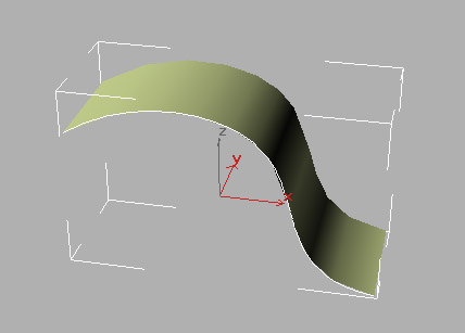
Before we go on, let's review how this very basic bit of modeling was achieved in MAX 2.5. MAX organizes NURBS models into baskets, and this can be very confusing. A NURBS Curve object in MAX can contain any number of NURBS curves. It's like a basket of NURBS curves. A NURBS Surface object can contain any number of NURBS curves and any number of NURBS surfaces as its sub-objectsÂonce again, a basket. This leads to some serious difficulties in communication. If we're going to keep things clear, we'll have to stick to some rules. I'll use the terms "NURBS Surface object" and "NURBS Curve object" (with Surface and Curve capitalized) to refer to the baskets, which are object-level entities in MAX. I'll speak of a "NURBS curve" or "NURBS surface" as a sub-object within a basket.
To create the original curve, you need to create a NURBS Curve object and draw the curve. Make it a CV curve. We'll consider MAX's point curves sometime later. Once you have a curve, you cannot make a NURBS surface out of it until you convert the NURBS Curve object into a NURBS Surface object, which can be achieved in the Modify Panel using the Edit Stack button. Now you'll have a NURBS Surface object that contains the curve as a sub-object. The curve can be extruded into a NURBS surface, which will be a second sub-object within the NURBS Surface object. Until you understand this system of organization, you won't be able to do anything.
| To Continue to Part 3, or Return to Part 1, Use Arrow Buttons |
|
Created: Apr. 14, 1999
Revised: Apr. 14, 1999
URL: https://webreference.com/3d/lesson64/part2.html
 Find a programming school near you