3D Animation Workshop: Lesson 28: VRML 97 Free Fall | 2
|
|
Lesson 28 - VRML 97 Free Fall - Part 3
Just as we can use the DEF tag to define the specific values in the fields of a node, we can define completely new node types built from existing nodes. In this example, we create a simple table with four legs. The essence of this example is the use of a prototype. A table node is defined using other nodes and called TwoColorTable. This is only the definition, however. There are as yet no tables in the scene.
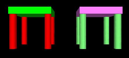
After the PROTO definition of the table is complete, that definition is then used to actually create two tables, using the new TwoColorTable node. Each table is in its own Transform, and each is translated one unit to the left and right, respectively, of the world transform center. Note how this differs from the DEF approach. DEF is used on nodes that actually exist in the scene so that they can be copied elsewhere. A PROTO statement defines a completely new node type, but nothing happens until the node is actually used in a scene.
Here is the code and the result.
#VRML V2.0 utf8
PROTO TwoColorTable   [  field SFColor legColor .5 1 .5
          field SFColor topColor 1 .5 1] #end of public interface
{
  Transform {
    children [
      Transform { # table top
        translation 0 .6 0
        children [
          Shape {
            geometry Box {size 1.2 0.2 1.2}
            appearance Appearance {
              material Material {diffuseColor IS topColor}
            }
          }#end of shape
        ]
      } #end of table top
      Transform { # first leg
        translation -.5 0 -.5
        children [
          DEF Leg Shape {
            geometry Cylinder {height 1 radius 0.1}
            appearance Appearance {
              material Material {diffuseColor IS legColor}
            }
          }
        ]
      }
      Transform { #second leg
        translation .5 0 -.5
        children [
          USE Leg
        ]
      }
      Transform { #third leg
        translation -.5 0 .5
        children [
          USE Leg
        ]
      }
      Transform { #fourth leg
        translation .5 0 .5
        children [
          USE Leg
        ]
      }
    ]#End of children of root transform
  }#End of root transform
}#End of PROTO
Transform {
    children [
    Transform {
      translation -1 0 0
      children [
      TwoColorTable {
        legColor 1 0 0
        topColor 0 1 0
      }
      ]
    }
    Transform {
      translation 1 0 0
      children [
        TwoColorTable {}
     Â
      ]
    }
    ] #end of world children
}#end of world transform system

CLICK HERE to load example if you have a VRML browser.
There is so much to learn here.
The PROTO statement is divided into two parts. The first part, in the square brackets, defines the fields that can be changed when the new node is actually implemented. In this case, these fields are the colors of the table legs and top. Default color values are supplied. When the two tables are implemented at bottom of the file, the first node inserts new colors (red and green) and the second node uses the default colors by failing to state any values. This is typical of VRML nodes. For example, we have seen that failing to enter a size value in a geometry node (like Sphere or Box) results in a default value of 1. Notice how the IS statement is used to connect the color names at the top of the PROTO definition with the applicable Material nodes deeper in the definition. For example, the diffuseColor of the first leg is the legColor parameter (whether the default value or any new value supplied when the PROTO is implemented).
This example also repeats what we learned in the previous one. A Shape node is named Leg using the DEF statement, and thus the other three legs are easily created as instances of the first. They share both the geometry and appearance of the first. This not only makes the code more readable, but assures that any change in the geometry or appearance of the first leg will be passed to all the others. Placing each leg in a separate Transform node permits them to be separately translated into position at the corners of the table. Likewise, assigning each entire table to a Transform permits each to move, rotate and scale as a single functional unit in the scene.
| To Return to Parts 1 and 2, Use Arrow Buttons |
|
Created: November 24, 1997
Revised: November 24, 1997
URL: https://webreference.com/3d/lesson28/part3.html


 Find a programming school near you